How to Select the Proper Power Supply for a DC Servo Motor
Introduction
When designing a system that uses DC servo motors, it is critical to select the proper power supply toensure reliable performance and protect system components. DC servo motors, which commonly operatewithin a 24VDC to 48VDC range, demand a power supply that can handle their unique requirements, such as precise voltage regulation, adequate current delivery, and protection mechanisms. This article provides a comprehensive guide to selecting the right power supply and incorporating an electronic fuse (e-Fuse) for optimal safety and performance.
Understanding DC Servo Motor Requirements
Servo motors are widely used in industrial automation, robotics, and precision equipment due to their ability to provide high torque, accurate positioning, and excellent speed control. Before choosing a power supply, it is essential to understand the motor’s electrical characteristics:
-
-
-
-
-
-
-
-
-
-
-
- Voltage Range: As mentioned above, DC servo motors typically operate within a rated voltage range (e.g. 24VDC to 48VDC). The power supply must be able to maintain a consistent voltage level to ensure reliable motor operation.
- Current Requirements: Servo motors draw varying currents depending on their load. Consider the motor’s continuous operating current and the peak current during start-up or under heavy-load conditions to ensure that the power supply can handle these currents.
- Ripple and Noise: Motors are sensitive to voltage ripples and electrical noise, which can affect their performance. A power supply with a low ripple and low noise levels is crucial for smooth motor operation.
-
-
-
-
-
-
-
-
-
-
Figure 1 shows the typical motor current under acceleration (denoted in red), constant speed (denoted in green), and deceleration (denoted in blue). Note that the motor current can be negative due to back electromotive force (EMF).
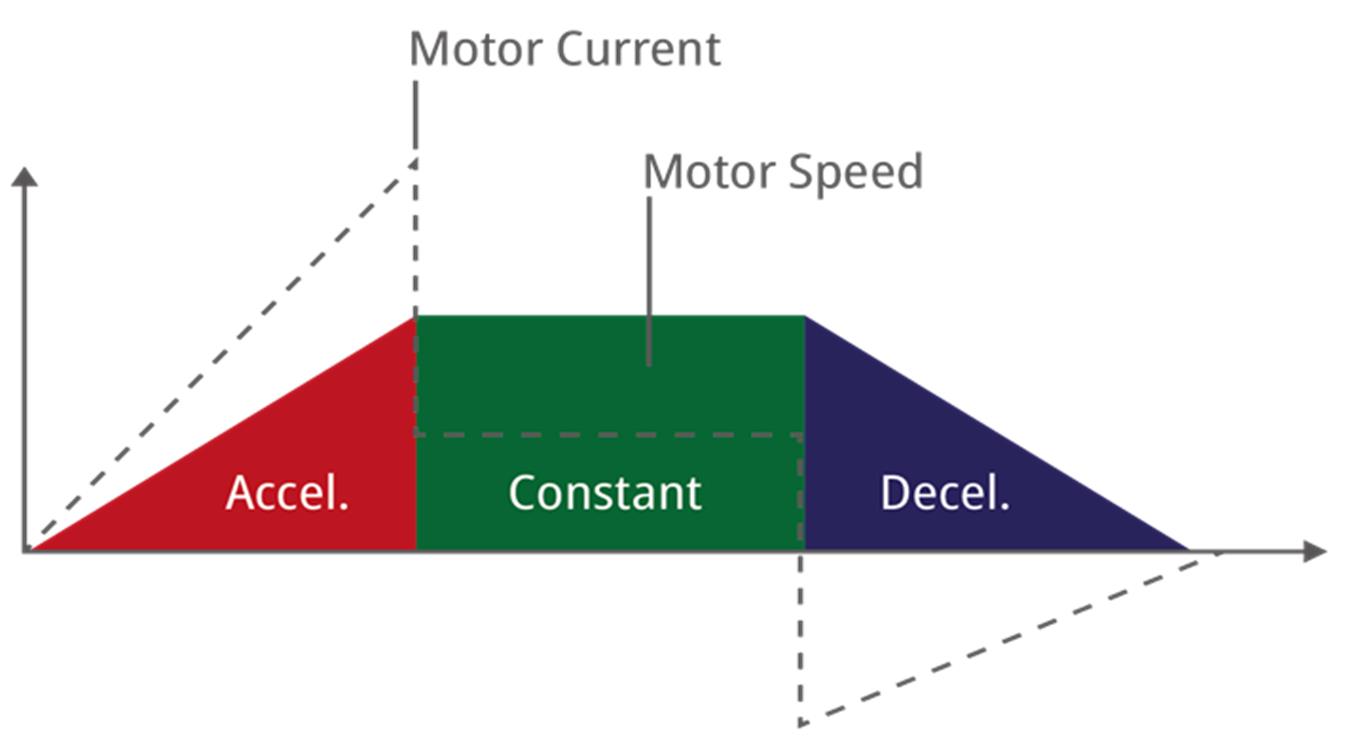
Figure 1: Typical Motor Current
Key Factors for Power Supply Selection
Voltage and Current Ratings
Select a power supply that delivers a stable voltage within the motor’s operating range. For the current, ensure that the supply can meet the motor’s peak demands. For example, if a motor requires 10A of continuous current and 20A during start-up, choose a power supply rated for 10A of continuous current that is capable of delivering at least 20A of peak current for the start-up duration (typically 20ms to 30ms).
Power Capacity
Calculate the power requirement (P) with Equation (1):
PCONT = V x IMAX_CONTWhere V is voltage, and IMAX_CONT is the maximum continuous current. Add a margin of about 20% to 30% to account for transient loads. For example, for a motor requiring 24VDC and 8A, the power supply should provide at least 24 x 8 = 192W of continuous power. When including the margin, the power supply should provide 250W for at least 10s. Allow for power derating with the worst-case ambient temperature.
Dynamic Load Response
High-efficiency power supplies reduce heat generation and energy consumption, which improve the system’s overall reliability and running costs.
Back EMF
If a motor is driven by the momentum of a spinning load, it will act as a generator and feed a back EMF voltage into the power supply output. The power supply must be able to withstand a back EMF voltage of 150% of the nominal output voltage (e.g. a 24V supply must withstand up to 36V on its output).
Protection Features
Over-voltage protection (OVP), under-voltage protection (UVP), over-current protection (OCP), and thermal protections are vital to prevent damage to the motor and power supply.
Efficiency
High-efficiency power supplies reduce heat generation and energy consumption, which improve the system’s overall reliability and running costs.
Incorporating an E-Fuse for Additional Protection
An electronic fuse (e-fuse) is a modern protection device that safeguards the motor and power supply against electrical faults by protecting from surges caused by over-current (OC) and over-voltage (OV) conditions.
Benefits of the RACPRO1 E-Fuse
-
-
-
-
-
-
-
-
-
-
-
- Individual OCP: Automatically disconnects the affected circuit during excessive current draw without interfering with the remaining circuits.
- Configurable Limits: Allow for the customization of current limits based on the application.
- Intelligent Short-Circuit Protection (SCP): Safely shuts off the circuit during a continuous short-circuit condition, but ignores high start-up currents to avoid erroneous tripping.
- Auto-Restart Capability: Can be configured for an automatic or manual reset after fault conditions.
- Handles Highly Inductive or Capacitive Loads: Motors are inductive loads and motor controllers often include large input capacitors. E-fuses can handle both high-inductance and high-capacitance loads.
-
-
-
-
-
-
-
-
-
-
Placing an E-Fuse in the Circuit
Install the e-fuse between the power supply and the servo motor. This ensures that any fault condition caused by the motor or wiring is isolated before it reaches the power supply.
A multi-channel e-fuse can be used to protect several motors connected to a common power supply with individual protection for each motor.
Selecting an E-Fuse
-
-
-
-
-
-
-
-
-
-
-
- Current Rating: Choose an e-fuse that matches the peak current of the motor while allowing for transient conditions.
- Voltage Rating: Ensure that the e-fuse can handle the maximum voltage of your power supply (e.g. 48VDC).
- Configurability: Select an e-fuse with adjustable parameters to tailor protection levels to your system.
-
-
-
-
-
-
-
-
-
-
Example Set-Up
Consider a system with four DC servo motors each rated for 24V, a continuous current of 3A, and a startup current of 6A (see Figure 2). The worst-case continuous current is 4 x 3A = 12A, but only if all four motors are active simultaneously.
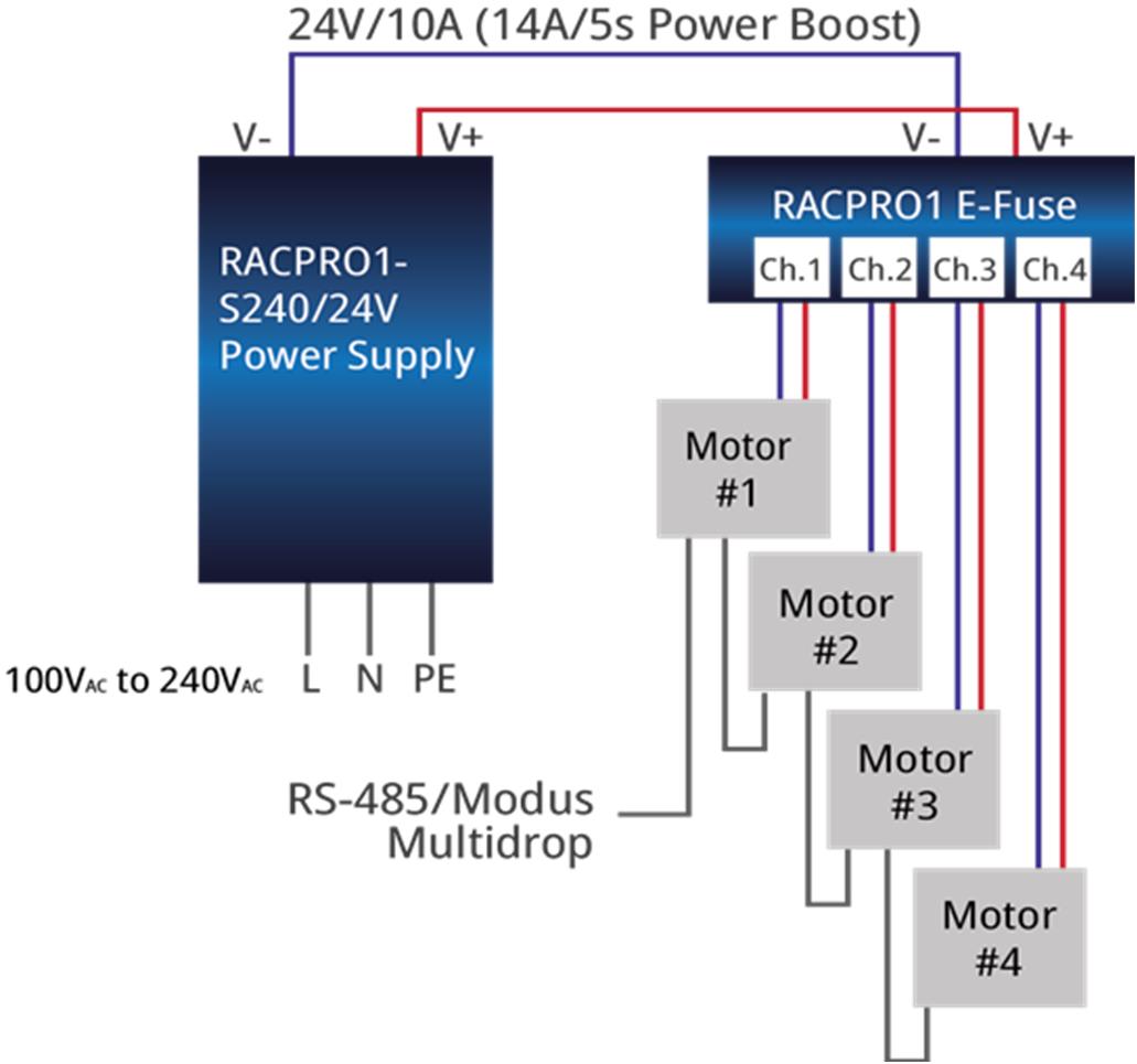
Figure 2: Four DC Servo Motors
Figure 3 shows the power supply (RACPRO1-S240/24), which is described in greater detail below:
-
-
-
-
-
-
-
-
-
-
-
- Voltage: 24V ± 5%. The ripple and noise < 1% of VOUT.
- Current: 12A of peak continuous current (with a safety margin, select a 14A peak-rated supply).
- Peak Power: 24V x 12A = 288W. A 240W power supply with a 140% power boost would be sufficient. An alternative would be to use a 400W rated power supply, but this would be more expensive and result in an over-dimensioned system that takes up more space.
- Start-Up Current: The worst-case start-up current is 4 x 6A = 24A.
-
-
-
-
-
-
-
-
-
-
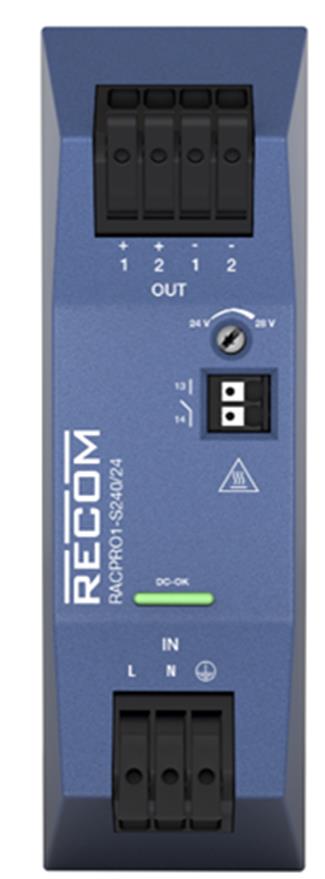
Figure 3: The RACPRO1-S240/24
Figure 4 shows the e-fuse (RACPRO1-4SP/24V/5A), described in greater detail below:
-
-
-
-
-
-
-
-
-
-
-
- Current Rating: 4 channels that each output 5A to handle individual peak loads safely.
- Voltage Rating: 24V.
- Features: Configurable current trip point, real-time output current monitoring, and fault reporting.
-
-
-
-
-
-
-
-
-
-
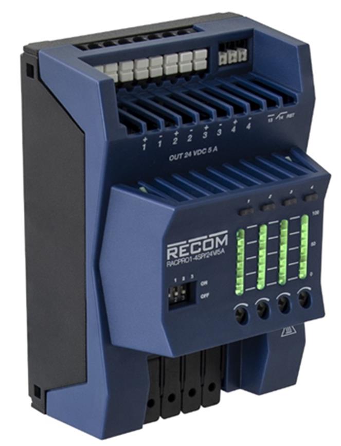
Figure 4: RACPRO1-4SP/24V/5A
Connect the power supply to the e-fuse following the configuration details below:
-
-
-
-
-
-
-
-
-
-
-
- Connect the e-fuse output to the servo motors.
- Each motor is independently powered with SCP, although all motors share a common power supply.
- A back EMF (BEMF) voltage up to 36V is tolerated without damage to either the e-fuse module or the power supply.
- The total start-up current capability is up to 25A/100ms.
- Individual motor channel start-up current of up to 7.5A without triggering OCP.
- Power boost current of up to 15A/5s.
-
-
-
-
-
-
-
-
-
-
Conclusion
Selecting the right power supply for a DC servo motor involves carefully considering the motor’s voltage and current requirements, as well as ensuring that the power supply has adequate capacity, efficiency, and protection features. Incorporating an e-fuse adds an extra layer of safety, protecting both the motor and the power supply from electrical faults.
By following these guidelines, you can design a reliable and efficient system that ensures optimal performance and longevity of your DC servo motor.
For more details, check out EZmotion’s integrated servo motors, Recom’s power supply rails, and Recom’s e-fuse devices.
Validate your login
Log in to your account
Create New Account