Using RS-485 and Modbus to Configure Servo Motors and Driver Modules
Introduction
Serial communication is a process in which data is continuously sent and received 1 bit at a time across a communication channel or computer bus. This communication process is utilized in most computer networks because it has fewer wires and is more cost-effective than parallel communication, in which multiple bits are sent on a link with parallel channels (see Figure 1).
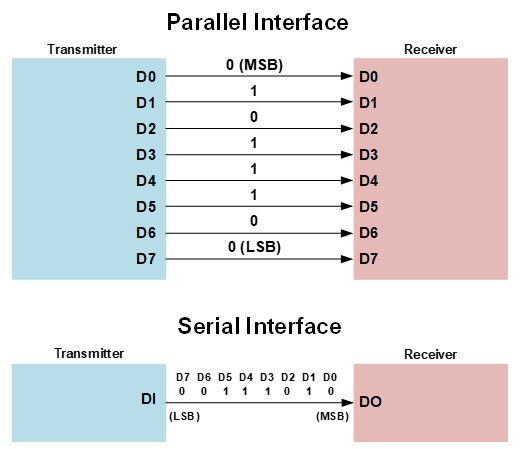
Figure 1: Parallel Communication vs. Serial Communication
A serial bus is comprised of two wires, or channels. One channel sends data (transmitter), while the other channel receives data (receiver). Serial communication can be further broken down into a synchronous interface and an asynchronous interface. The synchronous interface pairs its data line(s) to a clock signal, which is often faster but requires an additional wire between devices. An asynchronous interface transfers data without an external clock signal, which minimizes the number of wires.
This article will focus on asynchronous serial interfaces because they are more commonly used, with a particular emphasis on the RS-485 standard.
Serial Communication Standards
Regardless of the communication process, there are established standards to ensure that transmitters and receivers can communicate effectively in serial communication systems. The Electronic Industries Association (EIA) has created communication standards for asynchronous serial communication, starting with RS-232C and ending with RS-485 (see Table 1).
Table 1: RS-232C, RS-422A, and RS-485 Communication Standards
| Parameter | RS-232C | RS-422A | RS-485 |
| Connection Type | Point-to-point | Multi-point | Multi-point |
| Max connected devices | 1 driver, 1 receiver | 1 driver, 10 receivers | 32 drivers, 32 receivers |
| Max transmission rate | 20kbps | 10Mbps | 10Mbps |
| Max cable length | 15m | 1200m | 1200m |
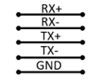
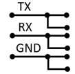
| Operation mode | Single-ended (unbalanced type) | Differential (balanced type) | Differential (balanced type) |
| Connection image | 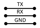 |
 |
 |
| Pros | • Most popular • Simplex |
• Long distance • Full duplex • 1:N connection |
• Long distance • Full duplex, half-duplex • N:N connection |
| Cons | • Short distance • Susceptible to noise • Slow data rate |
• Not common • One transmitter • Unidirectional |
• Requires terminating resistor |
EZmotion products use RS-485 communication because it is faster, provides excellent noise immunity, and can have up to 31 slave devices on the network.
RS-485 and Modbus
RS-485 is a transmission standard, meaning that it is a widely agreed upon set of guidelines for data communication. On the other hand, Modbus is a protocol, which is a set of rules and procedures that are agreed upon by the transmitter and receiver. Although they sound similar, a communication system implements a protocol to comply with a standard. In this scenario, the Modbus protocol allows transmitters and receivers to comply with the standards established in RS-485.
RS-485 is used to implement serial data communication while serving several devices that are attached to the same bus. Because it can be used for many devices (up to 32 transmitters and 32 receivers), has a long maximum cable length, and has a high maximum transmission rate, RS-485 is often used in computer and automation systems, industrial factories, and even theaters.
Modbus is a protocol that defines a means for the master and slave devices to communicate (see Figure 2). When Modbus is implemented in RS-485, communication is initiated by the master device when the master sends a query to the slave. The master can address a particular slave device, or it can send out a broadcast (or all call) address that can be received by all the slave devices on the network. A slave device cannot initiate communication with the master device. Rather, the slave device can only respond to the message it has received.
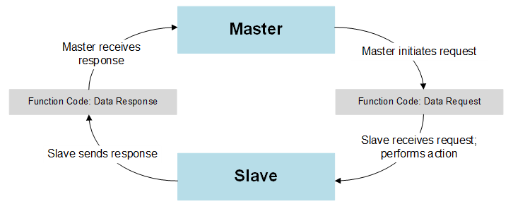
Figure 2: Master and Slave Communication
Modbus communication can be broken down into two types:
1. Modbus request: The request is generated by the master device and sent to the slave device(s). This request tells the slave device what action it needs to perform, and it can provide additional information that is required for the slave device to perform the relevant action. The data field tells the slave device what register to start at and how many registers to read.
In addition, the master device provides a code for cyclic redundancy check (CRC). The CRC request should match the CRC value by the slave device. When the CRC codes match, the slave device can verify that it has been sent valid data.
2. Modbus response: The slave device responds to the master device and sends the relevant information, or the slave device confirms that it has executed the requested action. If there is an error, the code changes to indicate that there has been an error, and the data bytes describe the particular error. The CRC allows the master device to confirm that it has received valid data.
The Benefits of Using RS-485
When trying to determine which control interface to use for your motor, it is vital to understand the benefits to using RS-485 compared to other control modes.
Step/direction mode requires two wires to control the step input, and two wires for the direction input. Therefore, a system with two motors would require a minimum of 8 wires to operate correctly. If using RS-485, users could daisy chain up to 31 devices with two wires. Fewer wires increases system reliability while reducing system size, and it can be easier to scale because there are fewer components to implement when adding additional motors. In addition, step/direction control requires dedicated outputs, while RS-485 can use existing communication channels that are present on most devices today.
I/O control requires a physical connection to change the input and output logic. An RS-485 interface allows users to access I/Os along with the full motor parameters and statuses.
Modbus RTU structure
Modbus RTU uses a client/server technique that can be applied to the master device and slave device. In this instance, the master device initiates a transaction (called a query) to one of the slave devices, which in turn replies with a response The master device can address individual slave devices or broadcast a message to all slave devices on the network.
The data frame format contains an address field, a function code, data, and a CRC (see Figure 3).
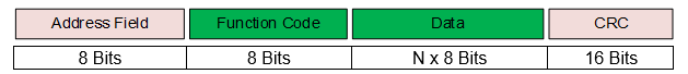
Figure 3: Modbus RTU Data Frame
If no error occurs, the slave device responds with a confirmation that the task is completed, data request, and an error checking field. If a communication error is detected, an exception response is sent. Figure 4 shows the exception data frame format.

Figure 4: Modbus Exception Data Frame
Controlling the Motor Using RS-485 Control
With RS-485 control, users can configure the motor position in absolute command mode or incremental command mode, set via the register. An absolute motor command commands the motor to an absolute position, while an incremental command moves the motor relative to its current position.
If the motor receives a new commanded position, the reference generation block in the device calculates the position curve periodically to ensure smooth motion (see Figure 5).
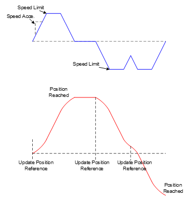
Figure 5: Position Reference Profile
The speed limit changes adaptively so that the position can be reached in the fastest time possible. A few example scenarios are described below:
• If the position can be reached at a faster speed, the motor increases its speed.
• If a motor cannot adequately speed up then slow down again to meet a certain position, it will maintain its speed.
• If the reference generation block determines that the motor will not be able to ramp down using the configurable speed slope, the motor slows so that its speed is zero once the position is reached.
• If the motor receives a new commanded position while the speed is ramping down, the reference generation block increases the speed again so that the motor can reach its target position as quickly as possible.
The MMS7xx-R1 and MMP7xx-R1 also provide speed control. In this mode, the speed (in rpm) is set to a target value. The velocity ramping up/down slope can also be configured. When the speed reference is updated, the motor’s speed ramps up or down to the target speed using the set slope rate. If this slope changes while the speed is ramping to its new level, the slope changes immediately and the motor uses this slope to reach the target speed. Figure 6 shows the speed reference profile.
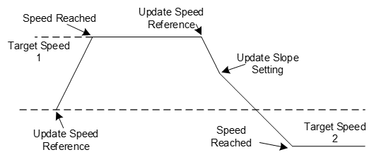
Figure 6: Speed Reference Profile
RS-485 and Modbus in EZmotion
EZmotion offers a robust portfolio of all-in-one servo motors and driver modules that use RS-485.
EZmotion’s servo motors include an integrated magnetic position sensor, field-oriented control (FOC), and are available in a wide range of sizes, power ranges, and operating voltages. Some models also come with parameter identification and control loop auto-tuning (see Figure 7).
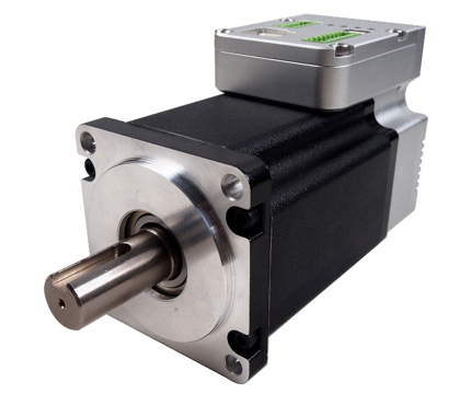
Figure 7: All-in-One Servo
Table 2 shows the all-in-one servo motors that use an RS-485 control interface (see Table 2).
Table 2: All-in-One Servo Motors with RS-485 Communication
| Part Number | Flange Dimension (mm) | Power (W) | Nominal Voltage (V) |
| MMS742038-24-R1-1 | 42 | 38 | 24 |
| MMS742052-24-R1-1 | 42 | 52 | 24 |
| MMS742077-24-R1-1 | 42 | 77 | 24 |
| MMS742105-24-R1-1 | 42 | 105 | 24 |
| MMS757094-36-R1-1 | 57 | 94 | 36 |
| MMS757141-36-R1-1 | 57 | 141 | 36 |
| MMS757188-36-R1-1 | 57 | 188 | 36 |
| MMS760200-48-R2-1 | 60 | 200 | 48 |
| MMS760400-48-R2-1 | 60 | 400 | 48 |
EZmotion’s driver modules are a total PCB module solution that integrate the power stage, position sensor, controller, and driver (see Figure 8). Similar to the all-in-one servo motors, the driver modules feature control loop auto-tuning, field-oriented control (FOC), and parameter identification.
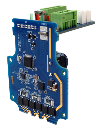
Figure 8: Driver Modules
Table 3 shows the driver modules that use an RS-485 control interface.
Table 3: Driver Modules with RS-485 Communication
| Part Number | Suitable Motor Size (mm) | Continuous Power (W) | Max Voltage (V) |
| MMP742038-36-R1-1 | 42 and 40 | 38 | 36 |
| MMP742052-36-R1-1 | 42 and 40 | 52 | 36 |
| MMP742077-36-R1-1 | 42 and 40 | 77 | 36 |
| MMP757094-70-R1-1 | 57 and 60 | 94 | 70 |
| MMP742105-36-R1-1 | 42 and 40 | 105 | 36 |
| MMP757141-70-R1-1 | 57 and 60 | 141 | 70 |
| MMP757188-70-R1-1 | 57 and 60 | 188 | 70 |
| MMP760100-75-R2-1 | 57 and 60 | 100 | 75 |
| MMP760200-75-R2-1 | 57 and 60 | 200 | 75 |
| MMP760400-75-R2-1 | 57 and 60 | 400 | 75 |
Conclusion
The RS-485 standard implements Modbus protocol to improve serial communication between master and slave devices. EZmotion provides a wide array of devices that can use this highly reliable communication style. Contact EZmotion for additional help and support, or to find the right all-in-one servo motor or driver module for your application needs.
Validate your login
Log in to your account
Create New Account