Servo-Powered Precision: Balancing Chaos with Control
Charan Bhamra
Introduction
This article introduces a demonstration system designed to highlight the capabilities of integrated servo motors in demanding, real-time, multi-axis motion control scenarios. Controlling a ping pong ball in motion may seem like a simple task, but it represents a real engineering challenge. The lightweight ball reacts drastically to the slightest disturbance, turning a playful object into a chaotic, fast-moving target. By precisely tilting a 3-axis parallel platform, this demonstration system brings order to chaotic motion, balancing, swirling, and bouncing a ping pong ball in real time utilizing EZmotion integrated servo motors.
Designing the Demonstration System
To showcase the performance of servo motors, a 3-axis parallel manipulator powered by EZmotion MMS740100-24-C2-1 motors was built as a demonstration system to balance, swirl, and bounce a ping pong ball using synchronized servo actuation, visual feedback, and real-time kinematic computation (see Figure 1).
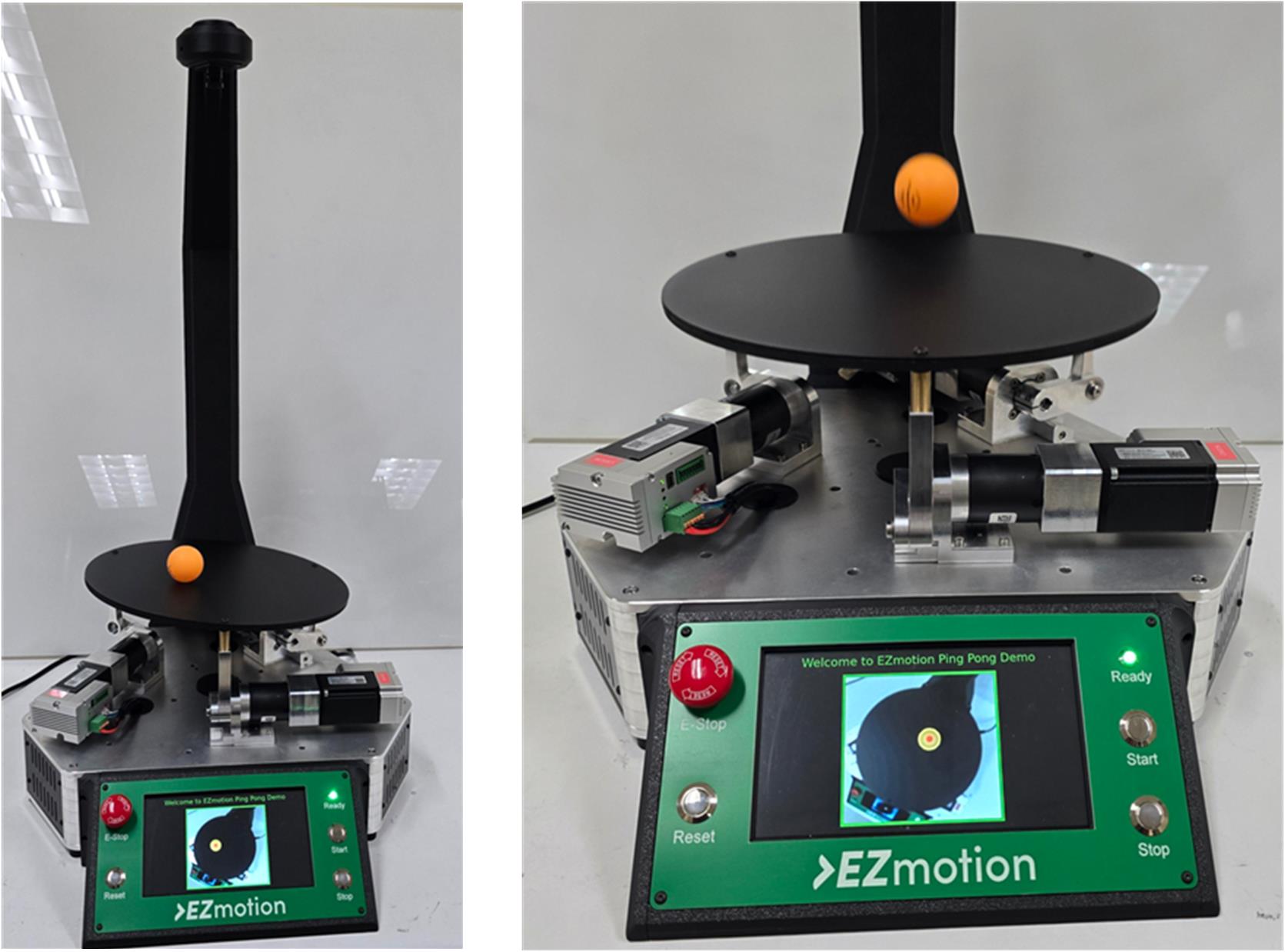
Figure 1: 3-Axis Parallel Manipulator Demo Powered by MMS740100-24-C2-1 Motors
The motors drive each limb of the platform with precision, implementing CANopen cyclic synchronous position (CSP) mode for tight coordination and jitter-free motion. Key challenges in the demonstration system include managing latency in visual feedback, maintaining synchronization across all axes, and running real-time inverse kinematics and proportional-integral-derivative (PID) control on embedded hardware.
System Architecture
A camera mounted above the demonstration system captures the ball’s position at a moderate frame rate of 40 frames per second (fps). This visual data is processed in real time, using OpenCV computer vision on a Raspberry Pi 5 device, to determine the ball’s actual location. The information is then fed to the Cortex M4 microcontroller unit (MCU) via serial peripheral interface (SPI) communication.
The embedded controller acts as the initiator controller for the motors, meaning that it is responsible for the system’s core control loop and kinematic model for the manipulator. Core control is built around a PID-based algorithm that converts position error into a precise platform tilt angle. First, the kinematic model is used to translate the platform tilt angle information into position targets for the three EZmotion MMS740100-24-C2-1 servo motors. Then the MMS740100-24-C2-1 motors enter CSP mode via the CANopen protocol to receive the position setpoints. This ensures synchronized and deterministic motion across all three axes, which is critical for stabilizing the platform in response to fast-changing inputs.
Figure 2 shows the manipulator system architecture block diagram.
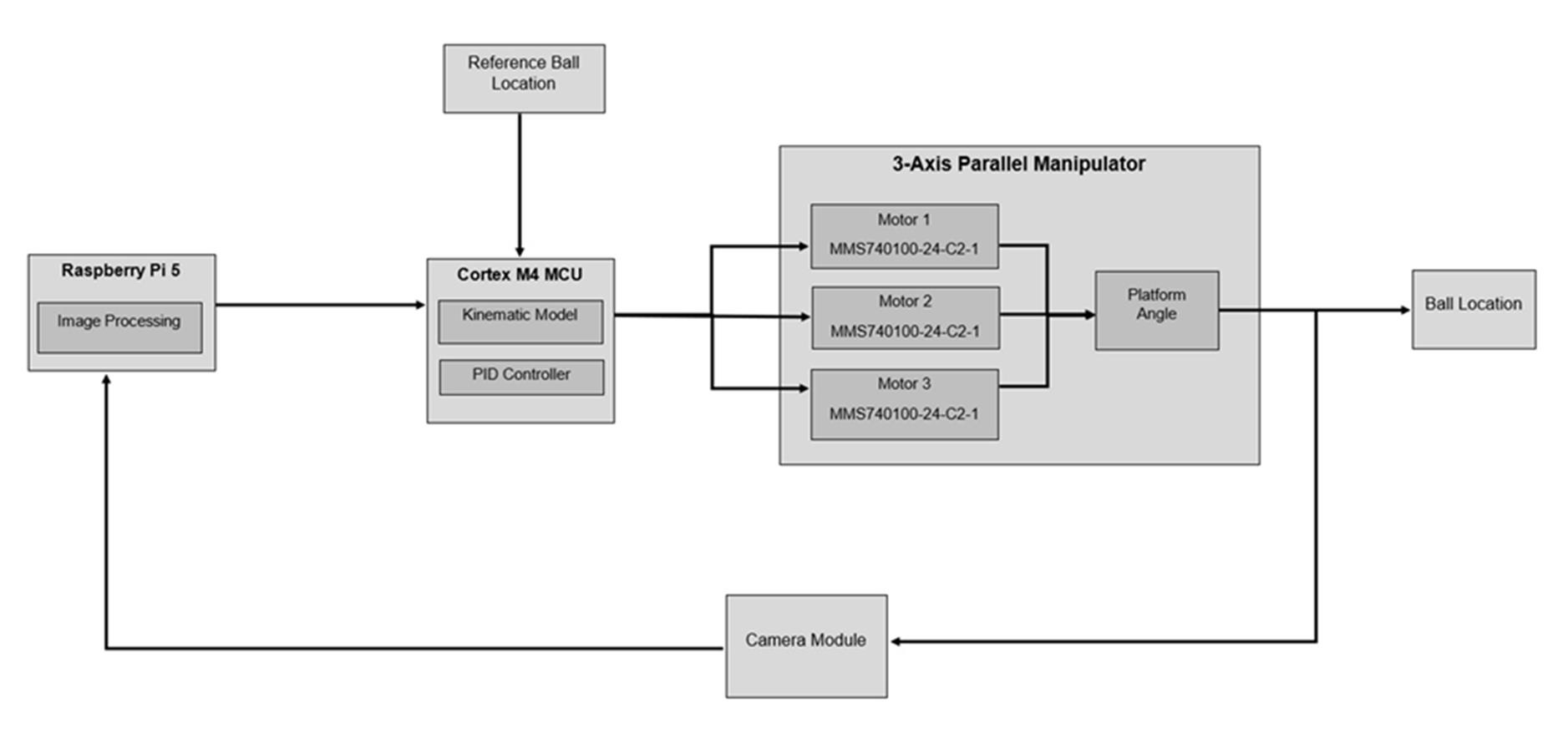
Figure 2: Manipulator System Architecture Block Diagram
Visual Tracking and Image Processing for Feedback
The manipulator system architecture separates computational roles between the microcontroller and Raspberry Pi 5 device. The MCU handles the inverse kinematics to drive the 3-axis parallel manipulator. The Raspberry Pi 5 device handles the visual feedback, running a lightweight Python script with OpenCV to process video frames from a top-mounted USB camera at 40fps. Gaussian blur is applied using OpenCV to the frames and converted to hue, saturation, and value (HSV) color space.
Furthermore, an orange color mask is applied to isolate the ping pong ball, and contour filtering is performed to identify the ball’s boundaries. The center coordinates are extracted from the smallest circle that completely encloses the largest contours. These coordinates are used for the ball position in the XY plane. To estimate the Z-position, the ball’s diameter information is used.
As the ping pong ball gets closer to the camera, its detected diameter in pixel units becomes larger. This pixel information is translated into a real-world Z-position in mm. The Raspberry Pi device is also connected to a local display via HDMI, providing live rendering of the camera feed with postprocessed ball tracking frames. The position and height data of the ball is sent to the MCU via the SPI.
Kinematic Model
Using the inverse kinematic approach, the motor crank angle is computed to achieve the desired platform tilt angle and Z translation. The global positions of the fixed-base joints and local positions of the moving platform joints distributed on a circle of a given radii can be calculated with Equation (1):

Equation (2), Equation (3), and Equation (4) calculate the rotation matrices that are used to calculate how the platform moves in 3D space. The rotation of a point around the X-axis by angle θx can be calculated with Equation (2):

The rotation of a point around the Y-axis by angle θy can be calculated with Equation (3):

The rotation of a point around the Z-axis by angle θz can be calculated with Equation (4):

The combined rotation matrix, which is the rotation of the platform’s axes to the base’s axes, can be calculated with Equation (5):
![]()
The actual positions of each platform joint in global coordinates can be calculated with Equation (6):

Once the global platform joint positions are determined, the required length of each limb can be calculated with Equation (7):
![]()
The length of each limb is the straight-line distance between the base joint and the transformed platform joint. Based on the required length of each limb, the motor crank angle with given lengths of the crank arm and the connecting rod can be calculated with Equation (8):

Figure 3 shows the linkage geometry of the 3-axis manipulator. The 3D view (left) shows the full 3D structure where each limb connects the fixed-base platform to the moving platform. The 2D view (right) isolates one limb, highlighting the key geometric parameters. These 3D and 2D views illustrate how Equation (1) to Equation (8) are used to compute the platform orientation and determine the required crank angle.
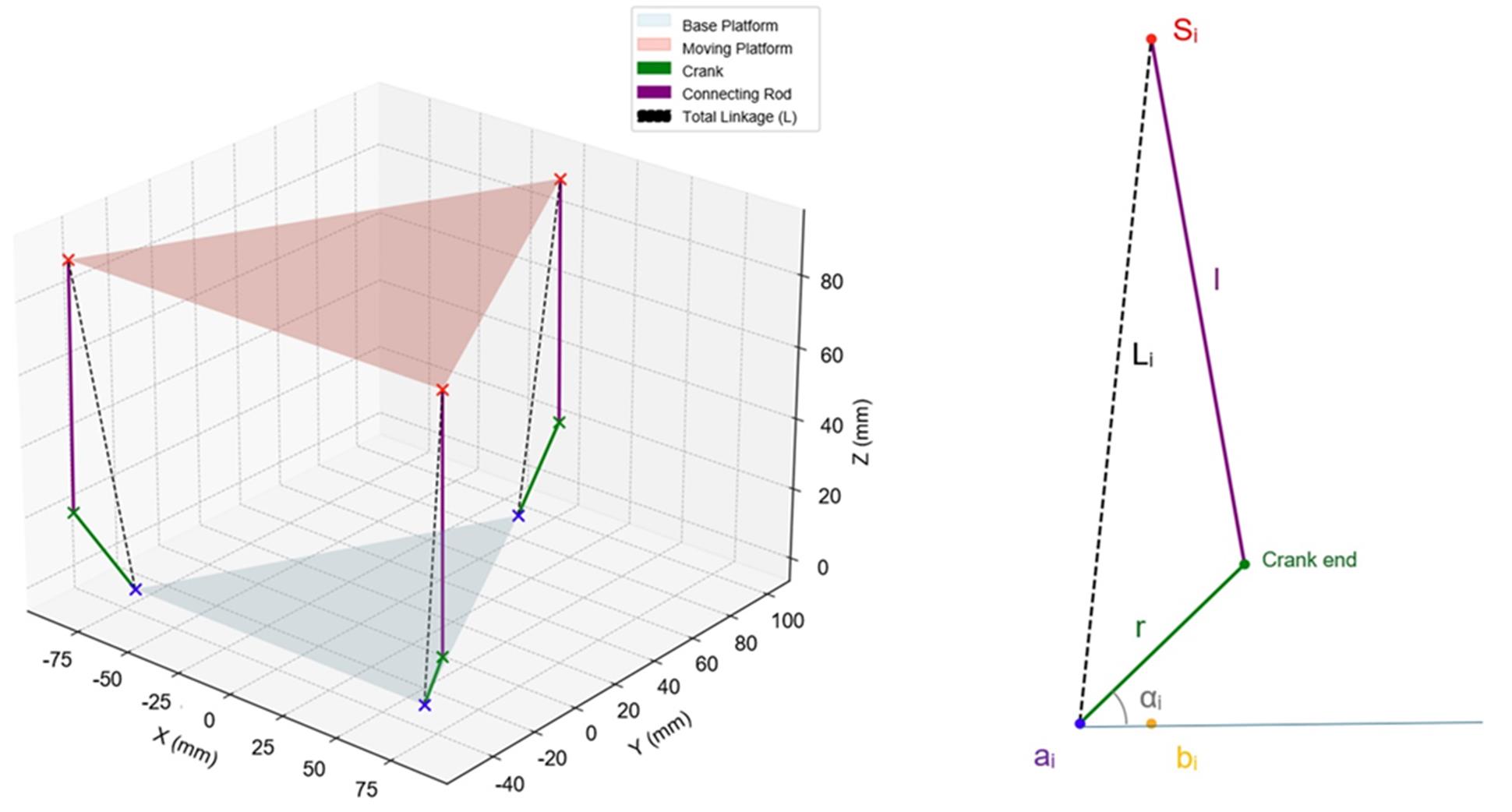
Figure 3: 3D View and 2D View of One of the Manipulator’s Limbs
The MCU runs a PID-based control system that continuously adjusts the tilt and Z translation of the platform to control the ball’s motion in real time. Depending on the mode (balancing, circular swirling, or bouncing), the independent PID controller for each mode computes the desired platform orientation and translation, which is then converted to absolute motor positions via inverse kinematics. The platform orientation and translation for each mode is described below:
-
-
-
-
-
-
-
-
-
-
-
- Balancing: The desired ball location is fixed at the center of the platform, and the PID controller minimizes the positional error by adjusting θx and θy accordingly.
- Circular swirling: The desired trajectory is set by the two-dimensional array containing predefined, time-varying reference points forming a circle of 100mm radius in the XY plane.
- Bouncing: The target height is set in mm units, and the target location is the center of the platform.
-
-
-
-
-
-
-
-
-
-
To initiate bouncing, the system enters an oscillation phase, where the platform undergoes rapid vertical movement to impart enough energy to lift the ball off the surface. This phase is designed to gradually increase the ball’s mechanical energy. Once a predefined energy threshold is reached, indicating that the ball is bouncing consistently, the controller transitions to bouncing mode. In this mode, the controller applies minimal synchronized vertical motion to sustain the bounce. The goal is to maintain the ball’s height with optimal energy efficiency rather than driving the ball higher.
The ball’s total energy can be estimated using both kinetic and potential energy components, and the ball’s velocity can be computed using the difference between the current and previous ball height over the timestep.
Inside the MMS740100-24-C2-1 EZmotion Motor
The MMS740100-24-C2-1 EZmotion integrated servo motor is designed to deliver precise, reliable motion control in a compact, all-in-one package (see Figure 4). It includes a 14-bit resolution magnetic position sensor that tracks the shaft’s position with sub-degree accuracy. In addition, the built-in servo driver delivers efficient power to the motor windings, and an embedded motion controller runs a nested control loop, regulating current, velocity, and position in real time. The onboard CAN transceiver enables direct integration of the CANopen network, while a dedicated power management solution ensures stable internal voltages for safe operation. By integrating all critical components — including the sensor, driver, controller, communication, and power into a single device — EZmotion motors eliminate the need for external boards and controllers, dramatically simplifying wiring and system architecture. The result is a plug-and-play solution that delivers precise, intelligent motion with minimal set-up.
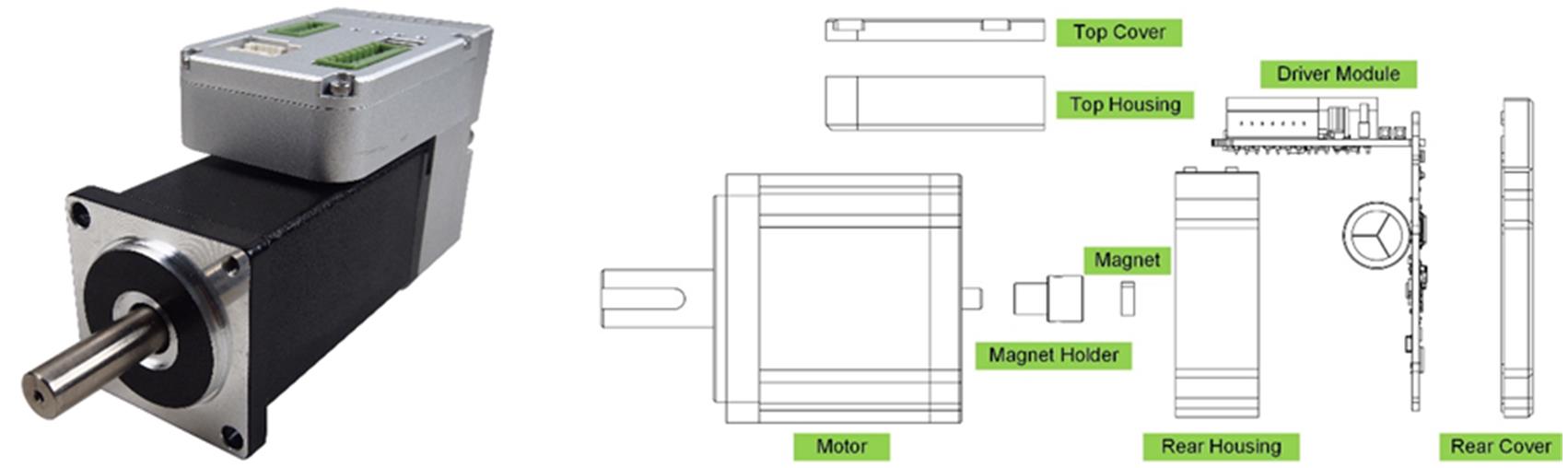
Figure 4: Photo and Exploded-View Drawing of the MMS740100-24-C2-1 Integrated Servo Motor
Synchronized Motion with Cyclic Synchronous Position (CSP) Mode
Synchronized motion is a high-precision actuation method supported by the CANopen protocol, and is achieved in the system using CSP mode, which is available on the MMS740100-24-C2-1. While other CANopen modes such as cyclic synchronous velocity (CSV) mode and cyclic synchronous torque (CST) mode are suited for velocity and torque-driven applications, CSP mode is ideal for deterministic position-based multi-axis control
In CSP mode, the MCU sends the precise position setpoints to each motor at a fixed and deterministic update rate. To ensure continuity and smoothness between updates, each motor internally performs linear interpolation between consecutive setpoints. The integrated motor controllers do not generate their own trajectories; instead, they rely on the initiator to continuously feed updated position targets (see Figure 5).
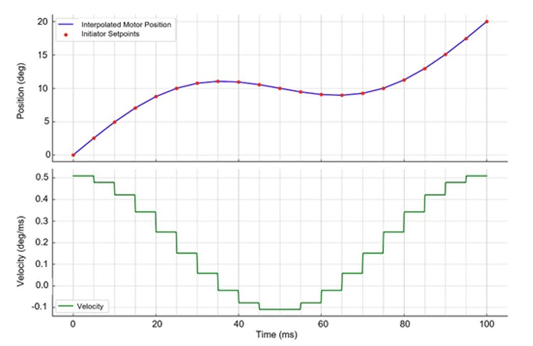
Figure 5: Example of the Position and Velocity Profile of a Motor in CSP Mode with Linear Interpolation
From a communication perspective, CSP mode requires the initiator to send process data object (PDO) messages containing absolute target positions. The PDO can be mapped, configured, and stored to the motor’s non-volatile memory (NVM). This enables the motor shaft to follow a seamless trajectory even though position targets are sampled at discrete intervals. The calculated crank angle values from inverse kinematics are converted into CSP position targets and broadcasted synchronously across the CAN bus. As a result, the system maintains highly coordinated and jitter-free motion across the three limbs.
Sequence of Operation
The system begins by executing a torque-based homing routine on the MMS740100-24-C2-1 motors to reference each motor’s initial position. During this process, all three limbs retract inward at a controlled speed until they reach their mechanical hard stops, ensuring a repeatable zero position. Once homing is complete, the platform automatically rises to a predefined mid-height along the Z-axis. A green status LED on the system indicates successful initialization and signals that the demo is ready for user interaction; specifically, the demo is ready for the ping pong ball to be placed onto the platform.
The demo enters its active sequence with balancing mode, then executes circular swirl mode for 30 seconds, followed by bouncing mode for 30 seconds. The sequence loops continuously as long as the system remains active. Throughout the demo, real-time ball tracking visuals are displayed on a 7-inch screen mounted to the front of the system, providing visual feedback of the ball’s motion.
Real-World Applications
The core motor technology showcased in this demonstration system has direct relevance to a variety of real-world applications that demand compact, precise, and coordinated motion control. Medical robotics implement similar architectures to stabilize endoscopic instruments, guide surgical tools, and assist in minimally invasive procedures where fine resolution and jitter-free motion are essential. In industrial automation, the same class of integrated servo motors powers systems including optical alignment stages, pick-and-place heads, and micro-assembly manipulators. Even in consumer electronics, delta 3D printers and delta pick-and-place machines employ a parallel kinematic structure (see Figure 6).
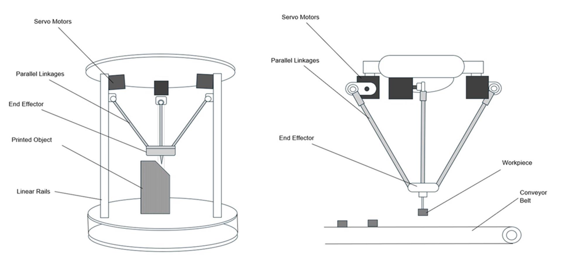
Figure 6: Delta 3D Printer and Delta Pick-and-Place Machine
Conclusion
This demonstration system serves as a proof-of-concept for the performance and integration advantages of servo power, using EZmotion’s MMS740100-24-C2-1 integrated servo motor as an example. Through the dynamic execution of balancing, swirling, and bouncing behaviors on the 3-axis parallel manipulator, the servo motors deliver high-resolution motion, real-time response, and tight multi-axis synchronization. Key features such as onboard drivers, angle sensors, and CANopen support with internal interpolation in CSP mode enable system simplicity and precision.
While the system demonstrates how visual data can be used to monitor multi-axis coordination and access motion accuracy in real time, its underlying architecture also mirrors the demands of real-world applications such as delta 3D printers, pick-and-place machines, medical robotics, and high-precision industrial motion control. This system demonstrates the capabilities of servo motors integrated into compact, high-performance mechatronic designs. For guidance on similar applications, motor selection, integration, or kinematic modeling, explore EZmotion’s full range of all-in-one servo motors.
Validate your login
登录您的账号
创建新账号